Fig. 1: ComBox fully assembled
Dimensions: 50x38x14mm (2x1.5x0.6 inch)
First, the bus-structure of the ComBox will be explained. After that
the constuction of each component and the use will be shown.
It is expected, that the reader is familiar with
basics of electronic circuts and has access to all equipment, that is nessecairy
for the construction and the test of electronic circuits in SMD.
Fig. 2 Bus-structure
The bus of the ComBox is very simple. On one end, a 9volts mains is
connected which supplies each ComBox on the bus. The boxes themselfs are
connected with a normal stereo 3.5mm headphone-connector and are attached
to the soundcards microphone-in of the corresponding PC. The microphone
of the headset is also connected to the ComBox and the headphone is plugged
into the soundcard.
Fig. 3: Schematic
The bus is connected at the connectors CON1 and CON2 and transfered
through the device without modifications. D1 and R11 form a visible function
control. The 9 volts-supply from the bus is low-pass-filtered trough R13
and C6 (D2 protects the circuit against reverse-polarity) and forms the
supply for opamp IC1.
Another low-pass-filter is applied to this voltage to generate a stable
supply for the pre-amp and surpress feedback. R5 and R6 generate the ground-potential
for the opamps. The signal of the condensor-microphone reaces the circuit
through CON3. R1 generates the supply for the microphone. The signal is
decoupled through C1 and amplified by T1, R2, R3, and R4.
This amplified signal is decoupled by C2, amplified by IC1Gate2 with
variable gain (R7, P1) and fed into the bus via R8 and C7. The bus-signal
is decoupled by C4 and amplified with opamp IC1Gate1. After that, it is
fed into the optocoupler OK1 which eleminates the galvanic connection between
the computers.
The bus itself is terminated with a 470ohms resistor. The reason for
this is, that with each connected ComBox the resistance of the bus and
therefore the overall volume decreases rapidly. But with this termination,
the much higher inner resistance of the boxes doesn't matter any more.
Fig. 4: Layout
The parts are applied to both sides (fig. 5). The SMD-parts are places
on ther soldering side and the wired parts are place on the placement-side.
The LED has to be soldered so that its bottom has a distance of 6mm (0.23")
from the board, so that it fits through a hole in the case.
The holes on the left and the right side of the board carry the pegs
from the case and therefore have to be big enough. Note that the ground
layer must not be cut.
Fig. 5: Placement placement-side... |
...and soldering side |
Fig. 6: The wholly assembled board seen from top... |
...and bottom |
PIN1 to PIN4 carry the mic-in cable to the soundcard. PIN1 and 2 are
ground, PIN3 and 4 carry the signal.
To protect the cable against pulling-forces, the cable can be glued to the board with super-glue.
| IC 1 | TL 072 SMD (SO8) |
| OK1 | Optocoupler PC817 |
| T1 | BC847C |
| D1 | LED 3mm green (or whatever you like) |
| D2 | LL4148 SMD |
| R1 | 5,6k SMD 0805 |
| R2, R10 | 1M SMD 0805 |
| R3, R5, R6 | 10k SMD 0805 |
| R4 | 100R SMD 0805 |
| R7 | 100k SMD 0805 |
| R8 | 4,7k SMD 0805 |
| R9 | 82k SMD 0805 |
| R11 | 820R SMD 0805 |
| R12 | 470R SMD 0805 |
| R13 | 150R SMD 0805 |
| R15 | 22k SMD 0805 |
| C1 | 220nF ceramic SMD 1208/1206 |
| C2, C3, C4 | 100nF ceramic SMD 1206 |
| C5, C6 | ELKO 100µF 10V RM 2 max. 7mm high |
| C7 | ELKO 4,7µF 50V RM 1,5 max. 7mm high |
| C9 | 1nF ceramic SMD 0805 |
| CON1, CON2, CON3 | 3,5mm headphone-plug |
| P1 | trimmer 500k / 470k |
| PIN1...PIN4 | 3,5mm-headphone-connector with cable |
| case | |
| short axis for trimmer |

Fig. 7: Frontside
The frontside-design is available in higher
resolution for printing. When you print it with 300dpi, you will get
original size. The printout is a little bit larger than the case and has
to be cut to size. This printout can also help drilling the frontside-holes.
Fig. 8: Modified mains-plug
Therefor the old plug is removed and a 3.5mm-headphone-plug with an
additional 470Ohms resistor is connected. The wiring-diagram is shown in
fig. 8.
One ComBox needs about 15mA and more than 300mA should not be transmitted
through the cable, so about 20 ComBoxes can be connected to one supply,
as long as the supply can source the required current.
You will need:
| 1 Mains 9volts min. 300mA |
| 1 3,5mm-stereo-headphone-plug |
| 1 470 Ohms-resistor 1/4 W |
Fig. 9: Microphone for an existing headphone
You will need:
| 1 elektret condensormicrophone |
| 1 3,5mm-headphone-connector |
| 2m one-wired shielded cable |
some design-stuff
6) Buscable |
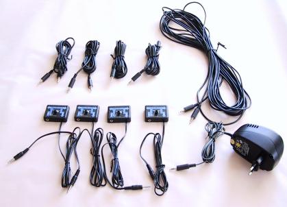
Fig. 10: Complete basic-set for four users
Warning: Don't change connections while powered on. These plan is provided "as is". No warranties! Use at your own risk!
You can get the whole page as Zip-File!
Have a lot of fun!
Back to mainpage